11.4.1. Transient dynamics of linear electrical grids with one dynamic component#
Guidelines for solution
Breaking down the solution:
Find the many-port equivalent of the linear algebraic part of the network (resistor, and prescribed generators), using PSCE. Find the relation between port voltage and currents and all the required variables of the network,
\[\begin{split}\begin{aligned} \mathbf{v}_{port} & = \mathbf{v}_0(\mathbf{e}, \mathbf{a}) + \mathbf{R} \mathbf{i}_{port} \\ \mathbf{z} & = \mathbf{z}_0(\mathbf{e}, \mathbf{a}) + \mathbf{z}_{/i_{port}} \mathbf{i}_{port} \end{aligned}\end{split}\]If 2 ports exist and port \(A\) is connected to a dynamical linear component and port \(B\) is connected to an ideal switch, the equations become to
\[\begin{split}\begin{aligned} v_A & = v_{0,A}(\mathbf{e},\mathbf{a}) + R_{AA} i_A + R_{AB} i_B \\ v_B & = v_{0,B}(\mathbf{e},\mathbf{a}) + R_{BA} i_A + R_{BB} i_B \\ \mathbf{z} & = \mathbf{z}_0(\mathbf{e}, \mathbf{a}) + \mathbf{z}_{/i_{port}} \mathbf{i}_{port} \end{aligned}\end{split}\]Evaluate the steady conditions for \(t \le 0^-\), with the given state of the switch (\(i_B = 0\) if it’s open, \(v_B = 0\) if it’s closed), and using the constitutive equation of the dynamical element (a capacitor acts as an open circuit in steady conditions, \(i_A = 0\) as \(i_A = C \frac{d v_A}{dt}\); an inductor acts as a short-circuit in steady conditions, \(v_A = 0\), as \(v_A = L \frac{d i_A}{d t}\)).
In the first two equations of the system, two of the four varaibles \(i_{A,B}\), \(v_{A,B}\) are thus known, and this system can be solved to find the other two quantities. Once \(\mathbf{i}_{port}\) is known, grid variables \(\mathbf{z}\) can be evaluated.
Transient dynamics is then evaluated using the change of state in the switch
\[\begin{split}\begin{aligned} \text{open to close: } & \begin{cases} v_{A}(t) = ( 1 - h(t) ) \, v_{A,0^-} \\ i_{A}(t) = h(t) \, i_{A,t\ge 0}(t) \end{cases} \\ \\ \text{close to open: } & \begin{cases} v_{A}(t) = h(t) \, v_{A,t\ge 0}(t) \\ i_{A}(t) = ( 1 - h(t) ) \, i_{A,0^-} \end{cases} \\ \\ \end{aligned}\end{split}\]and using the conditions for \(t \ge 0\) in the equations of the equivalent network to find the equivalent resistance \(R_{eq}\) of the algebraic part of the network to be used in the constitutive equations of the dynamical component,
\[\begin{split}\begin{aligned} \text{capacitor} &: && 0 = i_A + C \frac{d v_A}{d t} && \rightarrow \quad f(\mathbf{x}_{B}) = v_A + R_{eq} C \frac{d v_A}{d t} \\ \text{inductor } &: && 0 = v_A + L \frac{d i_A}{d t} && \rightarrow \quad f(\mathbf{x}_{B}) = i_A + R_{eq} L \frac{d i_A}{d t} \\ \end{aligned}\end{split}\]with \(f(\mathbf{x}_{B})\) a forcing term depending on the state of the switch, and the initial conditions for the state variable of the dynamical components equal to the steady conditions, as there’s no jump in state variables without impulsive forces.
Once the state variables of the dynamical equations are known. it’s possible to evaluate all the other required variables.
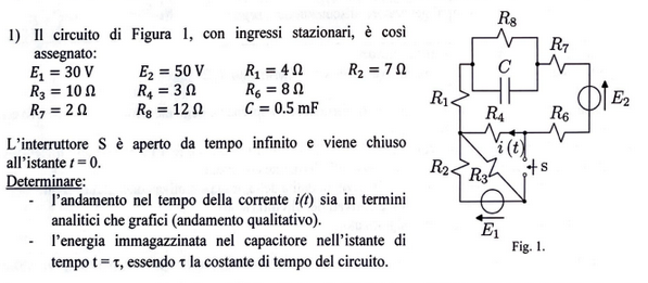
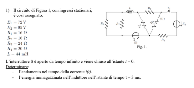
Exercise 11.1 (Exam 2025-02-11, Exercise 1.)
Solution
Following the guidelines for the solution, a many-port Thevenin equivalent circuit of the resistive part of the circuit is found, with two ports for interfacing with the capacitor (A) and with the switch. The dynamical equation of the system is written in state-space representation, writing the voltage at the ports and the unknown variable \(i(t)\) as outputs; the capacitor contitutive equation is used to find the time evolution of the system once the switch is closed
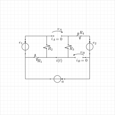
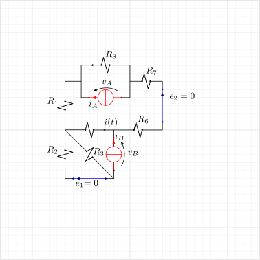
Internal generators on, open circuit
Solution using two loop currents, \(i_1\) in the upper part of the circuit and \(i_2\) in the lower triangle. Using KVL
so that the desired variables read
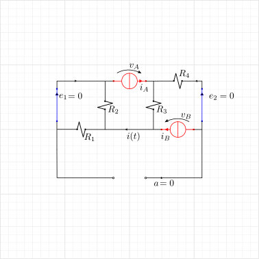
Internal generators off, current generators at the ports
Callling \(i_A\) and \(i_B\) the current passing through the current generators connected at the ports. The solution is found powering one generation at a time and then exploiting PSCE
Powering A …
Powering B. …
Currents in the two parallel branches in the upper part of the circuit (current dividers) read

The equations of the equivalent algebraic system are
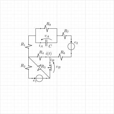
Steady solution for \(t \le 0^-\). With switch open \(i_B = 0\) and steady conditions \(i_A = C \dot{v}_A = 0\),
Transient dynamics, when the switch closes \(v_B(t \ge 0^+) = 0\),
Tension across the switch
\[\begin{split}\begin{aligned} v_{B}(t) & = v_{B,0} \, h(-t) \\ \Delta v_{B}(t) & = v_B(t) - v_{B,0} = - v_{B,0} \, h(t) \ . \end{aligned}\end{split}\]Tension across the capacitor. The dynamical equation for the difference of the state variable reads
\[\begin{split}\begin{aligned} 0 & = i_A + C \dot{v}_A = \\ & = \dfrac{R_3 + R_4}{\det \mathbf{R}} \Delta v_A(t) + \dfrac{R_3}{\det \mathbf{R}} \Delta v_B(t) + C \dot{v}_A \ . \end{aligned}\end{split}\]As \(v_{A}(t=0) = v_{A,0}\) (no jump in state variables without impulsive forcing), \(\Delta v_A = v_A - v_{A,0}\), and \(\frac{d}{dt} \Delta v_A = \frac{d}{dt} v_A\), the dynamical equation reads
\[\begin{split}\begin{cases} \dfrac{\det \mathbf{R}}{R_3 + R_4} C \dfrac{d}{dt}\Delta v_A + \Delta v_{A} = - \dfrac{R_3}{R_3 + R_4} \Delta v_{B}(t) = \dfrac{R_3}{R_3 + R_4} \, v_{B,0} \, h(t) \\ \\ \Delta v_A(0^-) = 0 \ . \end{cases}\end{split}\]\[\begin{aligned} \Delta v_A(t) & = \frac{R_3}{R_3 + R_4} v_{B,0} \left[ 1 - \exp\left( - \dfrac{t}{\tau} \right) \right] \, h(t) \ , \end{aligned}\]having defined the time constant and the equivalent reistence seen by the capacitor
\[\begin{split}\begin{aligned} R_{eq} & := \dfrac{\det \mathbf{R}}{R_3+R_4} = \dfrac{R_1 R_2}{R_1 + R_2} + \dfrac{R_3 R_4}{R_3 + R_4} = \frac{50}{21} \, V = 2.381 \, V \\ \\ \tau & := R_{eq} C = 1.1905 \, s \end{aligned}\end{split}\]Tension through the capacitor reads
\[\begin{split}\begin{aligned} v_A(t) & = v_{A,0} + \delta v_A(t) = \\ & = v_{A,0} + \Delta v_{A,+\infty} \, \left[ 1 - \exp\left( - \dfrac{t}{\tau} \right) \right] \, h(t) \ , \end{aligned}\end{split}\]so that the values
\[\begin{split}\begin{aligned} v_A(0^+) & = v_{A,0} = 7.67 \, V \\ v_A(+\infty) & = v_{A,0} + \Delta v_{A,+\infty} = ( 7.667 - 5.571 ) \, V = 2.095 \, V \ . \end{aligned}\end{split}\]Current through the capacitor.
\[\begin{split}\begin{aligned} i_A(t) & = \dfrac{R_3+R_4}{\det \mathbf{R}} \Delta v_A(t) + \dfrac{R_3}{\det \mathbf{R}} \Delta v_B(t) = \\ & = \dfrac{R_3+R_4}{\det \mathbf{R}} \frac{R_3}{R_3 + R_4} v_{B,0} \left[ 1 - \exp\left( - \dfrac{t}{\tau} \right) \right] \, h(t) - \dfrac{R_3}{\det \mathbf{R}} v_{B,0} \, h(t) = \\ & = - \dfrac{R_3}{\det \mathbf{R}} v_{B,0} \exp\left( - \dfrac{t}{\tau} \right) \, h(t) \\ & = 2.34 \, A \, \exp\left( - \dfrac{t}{\tau} \right) \, h(t) \ . \end{aligned}\end{split}\]so that the values
\[\begin{split}\begin{aligned} i_A(0^+) & = 2.34 \, A \\ i_A(+\infty) & = 0.00 \, A \end{aligned}\end{split}\]Current \(i(t)\)
\[\begin{split}\begin{aligned} i(t) & = i_{,0} + i_A(t) = \\ & = a - \dfrac{R_3}{\det \mathbf{R}} v_{B,0} \exp\left( - \dfrac{t}{\tau} \right) \, h(t) \\ & = 3.00 \, A + 2.34 \, A \, e^{-\frac{t}{\tau}} h(t) \ , \end{aligned}\end{split}\]so that the values
\[\begin{split}\begin{aligned} i(0^+) & = 5.35 \, A \\ i(+\infty) & = 3.00 \, A \end{aligned}\end{split}\]
Energy stored in the capacitor at \(t = 0\). Energy in the capacitor reads
At \(t = 0\), \(v_A(0) = 7.667 \, V\) and \(E_C(0) = 14.694 \, J \).
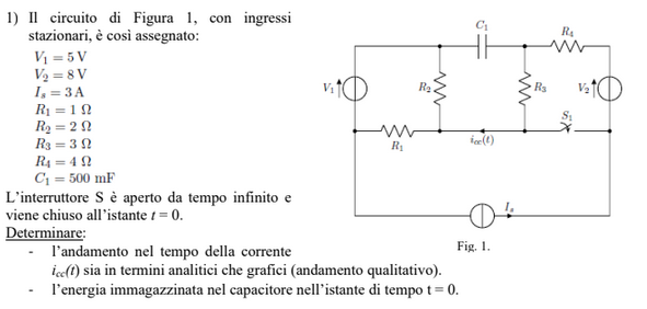
Exercise 11.2 (Exam 2025-01-22, Exercise 1.)
Solution
Following the guidelines for the solution, a many-port Thevenin equivalent circuit of the resistive part of the circuit is found, with two ports for interfacing with the capacitor (A) and with the switch. The dynamical equation of the system is written in state-space representation, writing the voltage at the ports and the unknown variable \(i(t)\) as outputs; the capacitor contitutive equation is used to find the time evolution of the system once the switch is closed

Internal generators on, open circuit
Solution using two loop currents, \(i_1\) in the upper part of the circuit and \(i_2\) in the lower triangle. Using KVL
with \(R_{14678} = R_1+R_4+R_6+R_7+R_8\), and \(R_{23} = R_2 + R_3\). The desired physical quantities are
and their values
Internal generators off, current generators at the ports
Callling \(i_A\) and \(i_B\) the current passing through the current generators connected at the ports. The solution is found powering one generation at a time and then exploiting PSCE
Powering A
Powering B.
Currents in the two parallel branches in the upper part of the circuit (current dividers) read
and the desired variables
The equations of the equivalent algebraic system are
and they can be used to write the currents as a function of the tensions
The switch command is off for \(t \le 0^-\), on for \(t > 0\),
Steady solution for \(t \le 0^-\). With switch open \(i_B = 0\) and steady conditions \(i_A = C \dot{v}_A = 0\),
Transient dynamics. For \(t \ge 0\), the switch is closed and thus \(v_B(t\ge 0^+) = 0\).
Tension across the switch as a function of time
\[\begin{split}\begin{aligned} v_{B}(t) & = v_{B,0} \, h(-t) = v_{B,0} ( 1 - h(t) ) \\ \Delta v_B(t) & = v_{B}(t) - v_{B,0} = - v_{B,0} \, h(t) \ . \end{aligned}\end{split}\]Tension across the capacitor. Writing \(i_A\) across the capacitor as a function of the tensions, the constitutive equation of the capacitor becomes
\[\begin{split}\begin{aligned} 0 & = C \dfrac{d \Delta v_A}{d t} + i_A = \\ & = C \dfrac{d \Delta v_A}{d t} + \dfrac{1}{\det \mathbf{R}} \left( R_{BB} \, \Delta v_A - R_{AB} \, \Delta v_B \right) \\ \\ \end{aligned}\end{split}\]\[\begin{split}\begin{cases} R_{eq} C \dfrac{d \Delta v_A}{d t} + \Delta v_A = \dfrac{ R_{AB} }{ R_{BB} } \, \Delta v_B(t) = - \dfrac{ R_{AB} }{ R_{BB} } v_{B,0} \, h(t) \\ \\ \Delta v_A(0) = 0 \ , \end{cases}\end{split}\]with
\[\begin{split}\begin{aligned} R_{eq} & = \frac{\det \mathbf{R}}{R_{BB}} = 6.8081 \, \Omega \\ \tau & = R_{eq} C = 3.4041 \cdot 10^{-3} \, s \\ \det \mathbf{R} & = 46.345 \, \Omega^2 \\ \end{aligned}\end{split}\]The solution of the differential equation provides the difference of the tension through the capacitor w.r.t. the initial steady condition
\[\Delta v_A(t) = \Delta v_{A,+\infty} \left( 1 - e^{-\frac{t}{\tau}} \right) \, h(t) \ ,\]with \(\Delta v_{A,+\infty} = -\frac{R_{AB}}{R_{BB}} v_{B,0} = 2.2742 \, V\). The voltage across the capacitor as a function of time \(t\) thus reads
\[\begin{split}\begin{aligned} v_A(t) & = v_{A,0} + \Delta v_A(t) = \\ & = v_{A,0} + \Delta v_{A,+\infty} \left( 1 - e^{-\frac{t}{\tau}} \right) \, h(t) \ , \end{aligned}\end{split}\]so that the values
\[\begin{split}\begin{aligned} v_A(0^+) & = v_{A,0} && = -20.69 \, V \\ v_A(+\infty) & = v_{A,0} + \Delta V = -20.69 \, V + 2.2742 \, V && = -18.4158 \, V \end{aligned}\end{split}\]Current through the capacitor.
\[\begin{split}\begin{aligned} i_A(t) & = \dfrac{1}{\det \mathbf{R}} \left( R_{BB} \, \Delta v_A(t) - R_{AB} \, \Delta v_B(t) \right) = \\ & = \dfrac{1}{\det \mathbf{R}} \left[ R_{BB} \, \left( -\frac{R_{AB}}{R_{BB}} v_{B,0} \right) \left( 1 - e^{-\frac{t}{\tau}} \right) \, h(t) + R_{AB} \, v_{B,0} \, h(t) \right] = \\ & = \frac{R_{AB}}{\det \mathbf{R}} v_{B,0} e^{-\frac{t}{\tau}} \, h(t) \ . \end{aligned}\end{split}\]so that the values
\[\begin{split}\begin{aligned} i_A(0^+) & = \frac{R_{AB}}{\det \mathbf{R}} v_{B,0} = \frac{-1.2414 \, \Omega}{46.908 \, \Omega^2} \, 12.475 \, V = -0.334 \, A \\ i_A(+\infty) & = v_{A,0} + \Delta V = -20.69 \, V + 2.2742 \, V && = 0.0 \, A \end{aligned}\end{split}\]or with \(i_A = - C \frac{d \Delta v_A}{dt}\)…
Current across the switch
\[\begin{split}\begin{aligned} i_B(t) & = \frac{1}{R_{BB}} \bigg[ v_B(t) - v_{B,0} - R_{BA} i_A(t) \bigg] = \\ & = \frac{1}{R_{BB}} \bigg[ - v_{B,0} - R_{BA} \frac{R_{AB}}{\det \mathbf{R}} v_{B,0} e^{-\frac{t}{\tau}} \bigg] \, h(t) = \\ & = - \frac{v_{B,0}}{R_{BB}} \bigg[ 1 + \frac{R_{BA} R_{AB}}{\det \mathbf{R}} \, e^{-\frac{t}{\tau}} \bigg] \, h(t) \ . \end{aligned}\end{split}\]so that the values
\[\begin{split}\begin{aligned} i_B(0^+) & = -\frac{v_{B,0}}{R_{BB}} \left[ 1 + \frac{R_{BA} R_{AB}}{\det \mathbf{R}} \right] = -\frac{v_{B,0} R_{AA}}{\det \mathbf{R}} = - \frac{7.0345 \, \Omega}{46.345 \, \Omega^2} \, 12.475 \, V = - 1.8929 \, A \\ i_B(+\infty) & = -\frac{v_{B,0}}{R_{BB}} = - \dfrac{12.475 \, V}{6.8073 \, \Omega} = -1.8320 \, A \ . \end{aligned}\end{split}\]Current \(i(t)\)
\[\begin{split}\begin{aligned} i(t) & = i_{0} - 0.4138 \, i_A(t) + 0.8966 \, i_B(t) = \\ & = i_{0} + \left[ - 0.4138 \, i_{A,0^+} e^{-\frac{t}{\tau}} + 0.8966 \, \left( i_{B,+\infty} + (i_{B,0^+} - i_{B,+\infty}) e^{-\frac{t}{\tau}} \right) \right] \, h(t) \ , \end{aligned}\end{split}\]so that
\[\begin{split}\begin{aligned} i(0^+) & = i_{0} - 0.4138 \, i_{A,0^+} + 0.8966 \, i_{B,0^+} = \\ & = -1.7214 \, A - 0.4138 \, (-0.334 \, A) + 0.8966 \, (-1.8929 \, A) = -3.2831 \, A \\ i(+\infty) & = i_{0} + 0.8966 \, i_{B,+\infty} = \\ & = -1.7214 \, A + 0.8966 \, (-1.8320 \, A) = - 3.3671 \, A \end{aligned}\end{split}\]
Energy stored in the capacitor.
and for \(t = \tau\),
and thus \(v_A(\tau) = -19.25 \, V\)
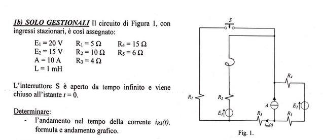
Exercise 11.3 (Exam 2024-09-06, Exercise 1.)
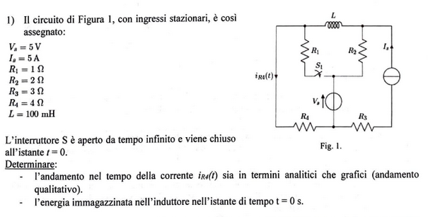
Solution
Equivalent 2-port circuit of the resistive network. Following the guidelines for the solution, a many-port Thevenin equivalent circuit of the resistive part of the circuit is found, with two ports for interfacing with the capacitor (A) and with the switch. The dynamical equation of the system is written in state-space representation, writing the voltage at the ports and the unknown variable \(i(t)\) as outputs; the capacitor contitutive equation is used to find the time evolution of the system once the switch is closed
open circuit
\[\begin{split}\begin{aligned} v_{A,0} & = - e - R_2 \, a = - 5 \, V - 2 \, \Omega \cdot 5 \, A = - 15 \, V \\ v_{B,0} & = - e = - 5 \, V \\ i_{0} & = 0 \, A \\ \end{aligned}\end{split}\]current generators at ports, internal generators off
\[\begin{split}\begin{aligned} v_A & = R_4 (i_A+i_B) + R_2 i_A \\ v_B & = v_A + R_1 i_B - R_2 i_A = R_4 (i_A + i_B) + R_1 i_B \\ i & = i_A + i_B \\ \end{aligned}\end{split}\]
and thus
Initial conditions. Steady conditions with open switch follows from conditions \(i_B = 0\), and \(v_A = L \frac{d i_A}{d t} = 0\), solving the equations for
Transient.
switch closes at time \(t = 0\). Voltage across the switch as a function of time can be represented by the function
\[\begin{split}\begin{aligned} v_{B}(t) & = v_B(0^-) \left( 1 - h(t) \right) \\ & = \left[ v_{B,0} - \dfrac{R_{BA}}{R_{AA}} v_{A,0} \right] \left( 1 - h(t) \right) \\ \Delta v_{B}(t) = v_{B}(t) - v_{B,0} & = - v_{B,0} h(t) - \dfrac{R_{BA}}{R_{AA}} v_{A,0} \left( 1 - h(t) \right) \\ \end{aligned}\end{split}\]dynamical equation of the inductor is written as a first order differential equation in the state variable of the inductor, \(i_A(t)\), after writing \(v_A\) as a function of \(i_A\) and the potentials at the ports,
\[\begin{split}\begin{aligned} v_A & = v_{A,0} + R_{AA} i_A + R_{AB} i_B = \\ & = v_{A,0} + R_{AA} i_A + \dfrac{R_{AB}}{R_{BB}} \left( v_B(t) - v_{B,0} - R_{BA} i_A \right) = \\ & = \dfrac{\det \mathbf{R}}{R_{BB}} i_A + v_{A,0} + \dfrac{R_{AB}}{R_{BB}} \left( v_B(t) - v_{B,0} \right) = \\ & = \dfrac{\det \mathbf{R}}{R_{BB}} i_A + v_{A,0} - \dfrac{R_{AB}}{R_{BB}} v_{B,0} \, h(t) - \dfrac{R_{AB}}{R_{BB}}\dfrac{R_{BA}}{R_{AA}} v_{A,0} (1- h(t)) = \\ & = \dfrac{\det \mathbf{R}}{R_{BB}} i_A + \dfrac{\det \mathbf{R}}{R_{AA} R_{BB}} v_{A,0} - \dfrac{R_{AB}}{R_{BB}}\left( v_{B,0} - \dfrac{R_{BA}}{R_{AA}} v_{A,0} \right) \, h(t) \end{aligned}\end{split}\]\[\begin{split}\begin{aligned} 0 = & L \dfrac{d i_A}{dt} + v_A \\ & L \dfrac{d i_A}{dt} + \dfrac{\det \mathbf{R}}{R_{BB}} i_A = - \dfrac{\det \mathbf{R}}{R_{AA} R_{BB}} v_{A,0} + \dfrac{R_{AB}}{R_{BB}} \left( v_{B,0} - \dfrac{R_{BA}}{R_{AA}} v_{A,0} \right) \, h(t) \end{aligned}\end{split}\]with initial conditions \(i_A(0) = i_A(0^-)\).
Numerical values
\[\begin{split}\begin{aligned} \tau & = \dfrac{L}{R_{eq}} = \dfrac{0.1 \, H}{2.8 \, \Omega} = 3.57 \cdot 10^{-2} \, s \\ R_{eq} & = \dfrac{\det \mathbf{R}}{R_{BB}} = \dfrac{14 \, \Omega^2}{5 \, \Omega} = 2.8 \, \Omega \\ \det \mathbf{R} & = R_{AA} R_{BB} - R_{AB} R_{BA} = \\ & = (R_1 + R_4)(R_2 + R_4) - R_4^2 = ( 30 - 16 ) \Omega^2 = 14 \, \Omega^2 \end{aligned}\end{split}\]Current through the inductor.
\[i_A(t) = \dots \]\[\begin{split}\begin{aligned} i_A(0) & = i_A(0^-) = 2.5 \, A \\ i_A(+\infty) & = \dfrac{1}{R_{eq}} \left[ - v_{A,0} + \dfrac{R_{AB}}{R_{BB}} v_{B,0} \right] = \dfrac{1}{2.8 \, \Omega} \left[ 15 \, V + \dfrac{4}{5} \, ( - 5 \, V ) \right] = 3.93 \, A \end{aligned}\end{split}\]Current through the switch.
\[i_B(t) = \dfrac{1}{R_{BB}} \left( v_B(t) - v_{B,0} - R_{BA} i_A(t) \right)\]\[\begin{split}\begin{aligned} i_B(0^+) & = \dfrac{1}{R_{BB}} \left( v_B(0^+ ) - v_{B,0} - R_{BA} i_A(0^+ ) \right) = \\ & = \dfrac{1}{5 \, \Omega} \left( 0 \, V + 5 \, V - 4 \, \Omega \cdot (2.5 \, A) \right) = -1.00 \, A \\ i_B(+\infty) & = \dfrac{1}{R_{BB}} \left( v_B(+\infty) - v_{B,0} - R_{BA} i_A(+\infty) \right) = \\ & = \dfrac{1}{5 \, \Omega} \left( 0 \, V + 5 \, V - 4 \, \Omega \cdot (3.93 \, A) \right) = -2.14 \, A\\ \end{aligned}\end{split}\]Current \(i_{R_4}\).
\[i_{R_4}(t) = i_A(t) + i_B(t)\]\[\begin{split}\begin{aligned} i_{R_4}(0^+ ) & = i_A(0^+ ) + i_B(0^+ ) = 2.50 \, A - 1.00 \, A = 1.50 \, A \\ i_{R_4}(+\infty) & = i_A(+\infty) + i_B(+\infty) = 3.93 \, A - 2.14 \, A = 1.79 \, A \\ \end{aligned}\end{split}\]
Exercise 11.4 (Exam 2024-07-22, Exercise 1.)
Solution - todo
Exercise 11.5 (Exam 2024-02-13, Exercise 1.)