11.4.2. Harmonic regime of linear electrical grids#
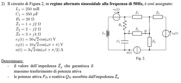
Exercise 11.6 (Exam 2025-02-11, Exercise 2.)
Solution
First one-port equivalent Thevenin circuit of the circuit with port \(A-B\) is evaluated, then power flow in harmonic regime is discussed.
Thevenin equivalent: voltage. With open circuit in \(A-B\), current \(a\) flows in the lower branch and in impedence \(Z_1\). Clockwise loop currents \(i_1\) and \(i_2\) flows in the left and right loop respectively. Kirchhoff voltage laws in the left and right loops give
and thus using Kirchhoff voltage law on the loop with nodes \(A-B\) and closing through \(Z_1\) and \(R_1\),
Thevenin equivalent: impedence. Opening circuit at the current generator, and replace tension generators with short circuits, the equivalent impedence is
Equivalent circuit. Kirchhoff voltage law on the equivalent circuit reads
and thus
Power. Complex power reads
Writing the impedence as \(Z_x = R_x + i X_x\), the active power reads
With the physical constraints \(R \ge 0\), the problem is a constrained optimization problem of finding the maximum value of the function \(P(R_x, X_x)\) subject to the constraint \(R_x \ge 0\),
The denominator is the sum of two non negative terms, one function of \(R_x\) and one function of \(X_x\). The independent variable \(X_x\) only appears in this term at the denominator, so that this term must vanish at the solution of the optimization problem, and thus
The remaining term is a function of \(R_x\) only and proportional to
Local extremes of this function is attained where
and thus, within the physical limit of the problem, the local and global maximum of the function (check that \(f''(\widetilde{R}_x) < 0\)), is attained for
and the maximum active power is
while the reactive power in this condition reads
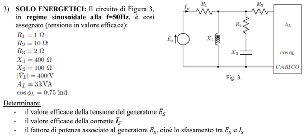
Exercise 11.7 (Exam 2025-02-11, Exercise 3.)
Solution
First power flow in harmonic regime is used to calculate load impedence, then the electrical circuit is solved, and the power on the tension generator is computed.
Load impedence \(Z_L\). Load impedence appears in the load constitutive equation \(V_L = Z_L I_L\), and can be evalauted from data about complex power,
Current \(I_s\). From data of load power, it’s possible to evaluate the current \(I_s\). The current \(I_L\) through the load reads
The three parallel sides act as current divider so that
and thus
Equivalent circuit. The impedence of the circuit powered by the tension generatore is
Given the equivalent impedance, and the current \(I_s\) the voltage across the tension generator is
and the power factor is \(\cos \varphi_s = \dots\), where
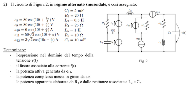
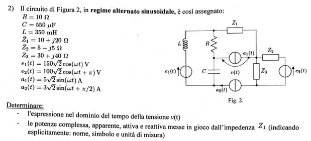
Exercise 11.8 (Exam 2025-01-22, Exercise 2.)
Solution
First one-port equivalent Thevenin circuit of the circuit with port \(A-B\) is evaluated, then the equivalent circuit is solved to find the tension \(v(t)\) across the current generator, and power flow in harmonic regime is discussed.
Thevenin equivalent: voltage. With an open circuit, the network can be split into two parts: the triangle in the upper-left side and the section in the right part.
In the triangular part, a current \(I_{a}\) flows in counter-clockwise direction, while current \(I_b\) flows in the right part in clockwise direction,
as
with \(Z_k\) being the impedence of the \(k\)-th side. Thevenin voltage thus reads
Thevenin equivalent: impedence. Equivalent impedence reads
Equivalent circuit. Prescribed current \(A_1\) flows in the equivalent circuit, and the voltage across the current generator is evaluated with Krichhoff voltage law
Signal in time is reconstructed using using the relation between effective and maximum amplitude of the oscillation and evaluating the real part of the signal \(|V_{A_1}| e^{i(\Omega t + \varphi_{V_{A_1}})}\)
Poer. Using definitions of power in circuits in harmonic regime,
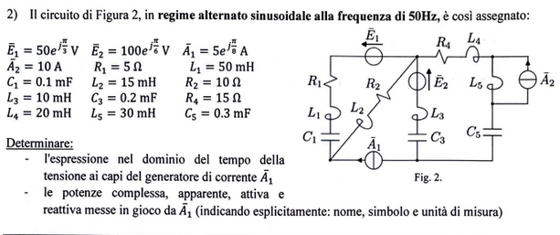
Exercise 11.9 (Exam 2024-09-06, Exercise 2.)
Solution - todo
Exercise 11.10 (Exam 2024-07-22, Exercise 2.)